
In a previous demo we presented a deringing filter for Daala that was based on a painting algorithm. Like many other things we tried in Daala, the idea seemed promising, but didn't make it in the end. More specifically, it had the following problems:
This brought us searching for a different algorithm, with the constraint that it had to be easy to vectorize. The resulting algorithm is called the conditional replacement filter, a non-linear filter loosely inspired from median filtering and from a degenerate bilateral filter.
Like other demos, this deringing filter demo skips all the math details to focus on the general principles of the algorithm. For those interested in all the technical details, see the full paper.
The main goal of deringing is to filter out ringing, while retaining all the details of the image. The amount of ringing tends to be roughly proportional to the quantization step size. The amount of details is a property of the input image, but the smallest details actually retained in the decoded image tends to be roughly proportional to the quantization step size. For a given quantization step size, the amplitude of the ringing is generally less than the amplitude of the details.
A standard linear filter works by averaging nearby values of the input to produce an output. For example, a 3-tap filter can be as simple as averaging the sample x(n) being filtered with its two neighbours: y(n) = (x(n-1) + x(n) + x(n+1))/3. This works well when we want to eliminate all high frequencies, but in the video context, it has the side effect of blurring out all details.
The conditional replacement filter (CRF) operates by excluding from the averaging the pixel values that are too different from the filtered pixel x(n) to be just ringing. It uses a threshold T to decide whether a pixel value is close enough. Any value that differs by more than T is replaced (in the filter computation only) by the value of the center pixel.
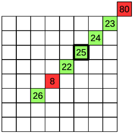
The interactive demo below shows how a single value x(n) is being filtered, with a 7-tap CRF, depending on the value of its neighbours. For a signal with N samples, the same calculation would be applied N times.
| Threshold | T | |||||||
| Sample position | n - 3 | n - 2 | n - 1 | n | n + 1 | n + 2 | n + 3 | i |
| Input | x[i] | |||||||
| Replacement mask | mask = abs(x[i]-x[n]) < T | |||||||
| Replaced value | 26 | 8 | 22 | 25 | 24 | 23 | 80 | r[i] = mask ? x[i] : x[n] |
| Linear filter output | 30 | y[i] = sum(x[i])/7 | ||||||
| CRF output | 25 | y[i] = sum(r[i])/7 |
You can change the input values in the boxes above and see how the affect the output of the filter. The linear filter output is the arithmetic average of the input values. The CRF output is the arithmetic average of the replaced values.
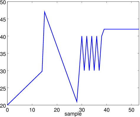
Now let's look at what the filter does to a one-dimensional signal with both smooth areas and sharp discontinuities (edges).
|
|
|
Original signal |
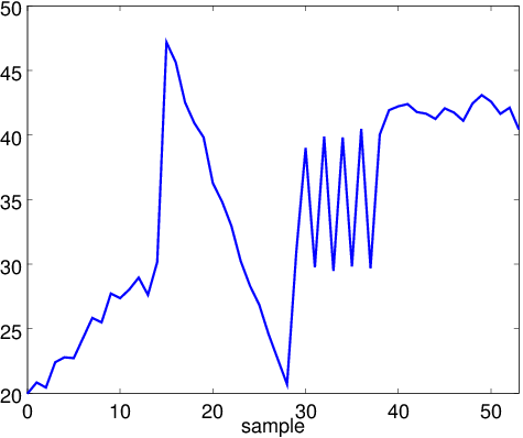
Original signal plus added noise (ringing) |
|

|
|
Noisy signal filtered with a linear (averaging) filter |
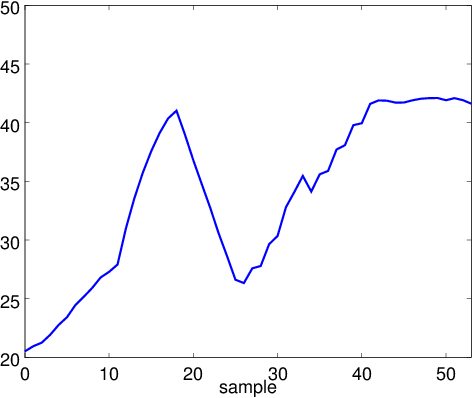
Noisy signal filtered with the CRF |
Although the conditional replacement filter is good at preventing blurring, it is far from perfect. The best way to help it is to apply it along the same direction as the main edge or pattern in each block. The decoder finds the direction that minimizes the difference between the decoded block and a perfectly directional pattern based on the decoded block.
Here is an example of a 8x8 block containing a line. The goal is to compute the direction of the line.
| Input block |  |
|||||||
| Direction |  |
 |
 |
 |
 |
 |
 |
 |
| Pattern |  |
 |
 |
 |
 |
 |
 |
 |
| Error (RMS) | 87 | 69 | 12 | 61 | 85 | 83 | 82 | 83 |
Fortunately, we don't have to actually compute the patterns above. Thanks to a set of algebraic simplifications, the direction search can be computed efficiently, with very few multiplications, and while taking advantage of SIMD instructions.
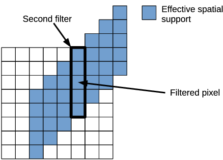
Once we know the direction in each block, we can start the actual deringing. For each pixel in the block, we use 3 pixels on each side, following the detected direction. The filter is allowed to use pixels that lie outside of the block, as shown below. The use of a direction makes it less likely to filter across an edge, but even if there is an edge, the CRF can avoid blurring it out.
So after being really careful to only filter along the direction of edges and patterns, the second stage of the deringing filter involves running the filter... right across these edges. The idea here is that for flat areas, a 7-tap filter may not be sufficient to remove all ringing. The idea of the second filtering step is to combine more pixels in the averaging. With a 7-tap initial filter and a 5-tap second stage filter, we end up with an effective filter of 35 taps in 2 dimensions. This is enough to remove almost all ringing in many cases. However, since this time the CRF is running across edges, we have to be very careful. For this reason, the threshold used in the second filtering step is much smaller than that used in the first step.
Each 8x8 block applies the exact same operations to every pixel, and all memory accesses are made with exactly the same offsets relative to a pixel's address, making SIMD support trivial.
So far we have described how the deringing process works, but without defining what threshold should be used. The threshold value is very important, as it determines which details are important and which should be considered as ringing and removed. If we set it too low, we won't remove the ringing, but if we set it too high, we will blur out the image. The main factor that affects the threshold calculation is the quantizer step size, in other words, the bitrate. At low bitrate (large quantizer) we want to use large threshold and at high bitrate (small quantizer) we want to use a small threshold.
Even with a good estimate of the optimal threshold, it's hard to always get it right. For this reason, we also have a per-superblock (64x64) threshold adjustment that we can apply to the computed threshold. This adjustment can make the threshold smaller, larger, or completely disable the deringing filter. The encoder chooses the threshold that maximizes quality for a particular superblock. It is the only information that the encoder has to send to the decoder for deringing and it amounts to about 2 bits per superblock, or about 128 bytes for an entire 1080p keyframe.
The figure below shows how the deringing adjustment is set on a real image.

On P-frames and B-frames, the deringing filter is never applied to blocks where no coefficients are coded (i.e. those that are based only on motion compensation), so the signalling cost is also lower.
In terms of objective metrics, the deringing filter can reduce the rate of video by about 4% to 8% for equal quality. For still images, the improvement range from 1% to 4%.
Now, here's what the filter actually looks like on one of the images that gave Daala the hardest time in the PCS 2015 image compression challenge.


Original
No deringing
Deringing
JPEG
Now that Mozilla is part of the Alliance for Open Media (AOM), we are integrating technology from Daala into the new AV1 codec. This new codec combines technology from Google's VP9 codec, Cisco's Thor codec, our Daala codec, as well as new technology developped within AOM. For this reason, we are now putting significant effort into the AOM project. We will also continue to improve Daala and use it as a research test bed for new coding techniques.
The deringing filter has just been ported to AV1 and already shows quality improvements. As a results of a hardware feasibility review conducted as part of the AOM process we were able to make simple changes to the algorithm that greatly reduce the hardware requirement without affecting quality. These changes will be merged back into Daala shortly.
—Jean-Marc Valin (jmvalin@jmvalin.ca) April 6, 2016arXiv:1602.05975 [cs.MM], 2016.